
PRODUCT CATEGORY

COMPANY PROFILES
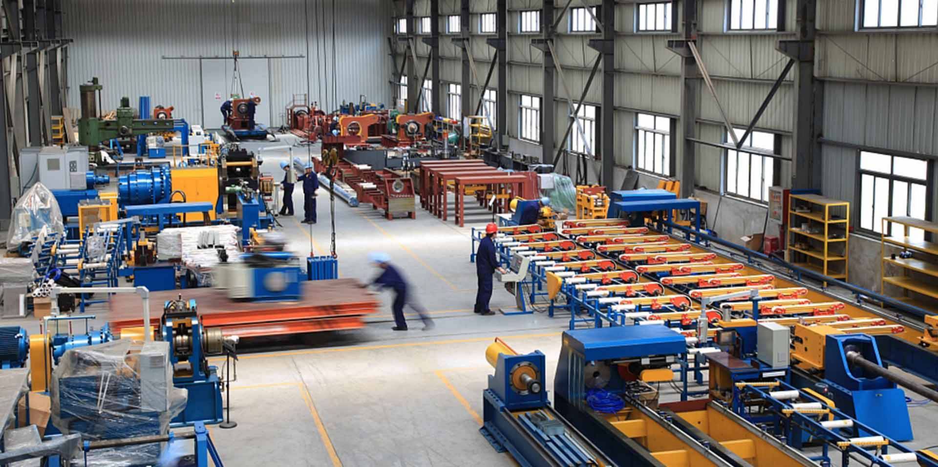
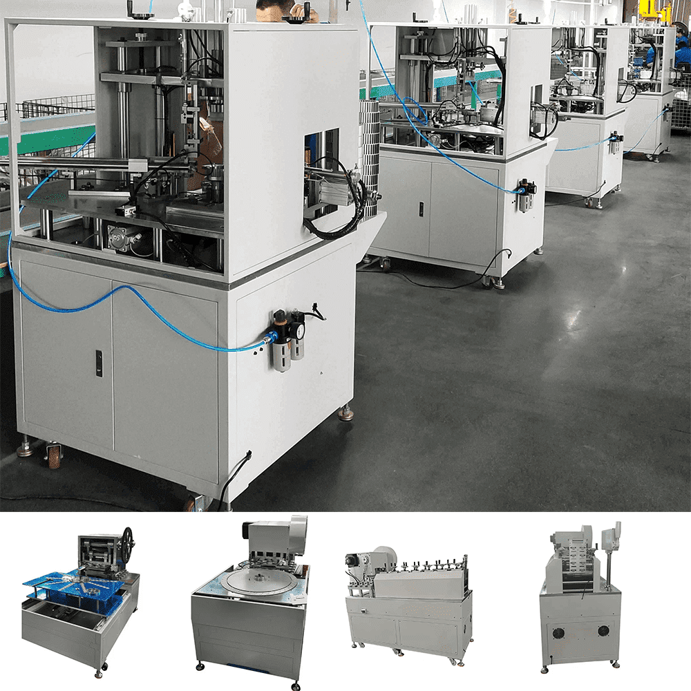
Altron is a developer and manufacturer of Metal Forming & Welding Automation Machines & Production Lines!
Fast Engineer Technical Services!
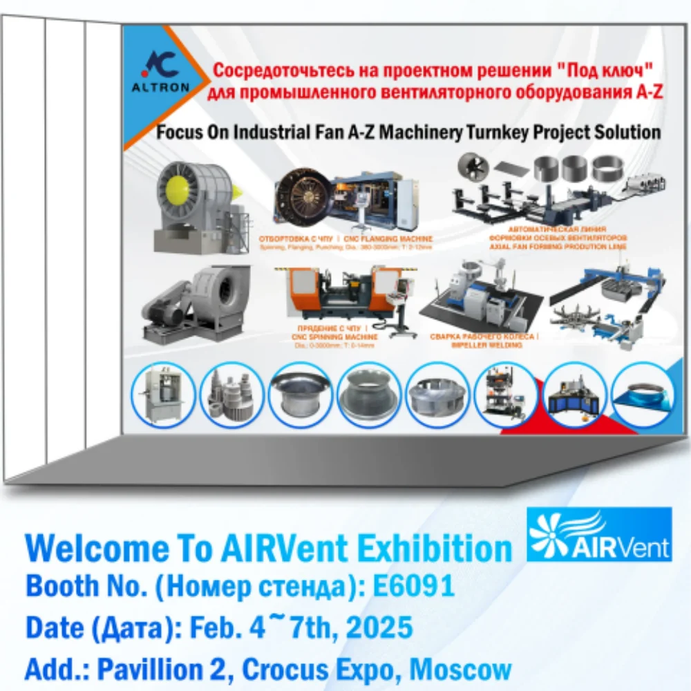
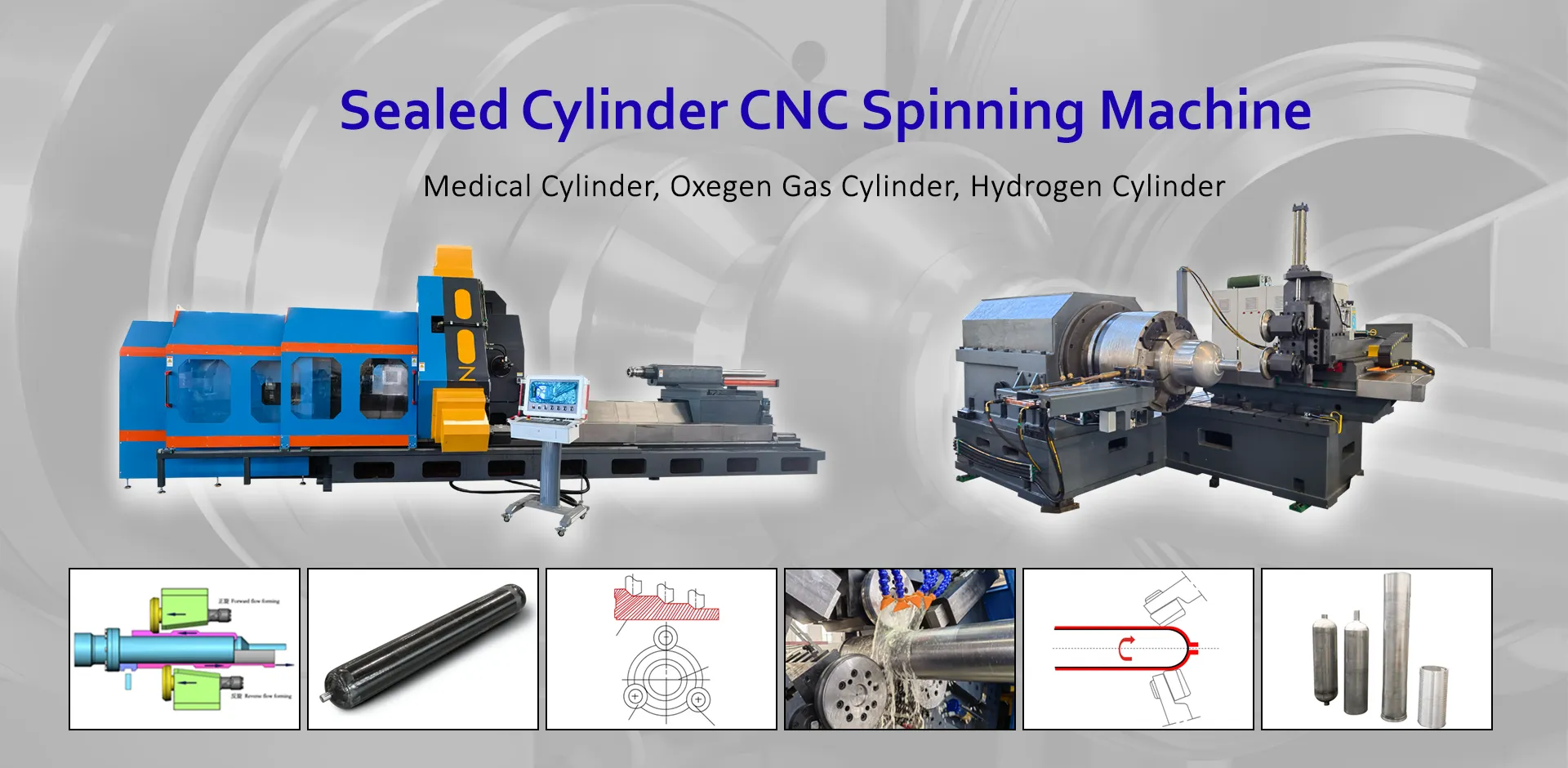
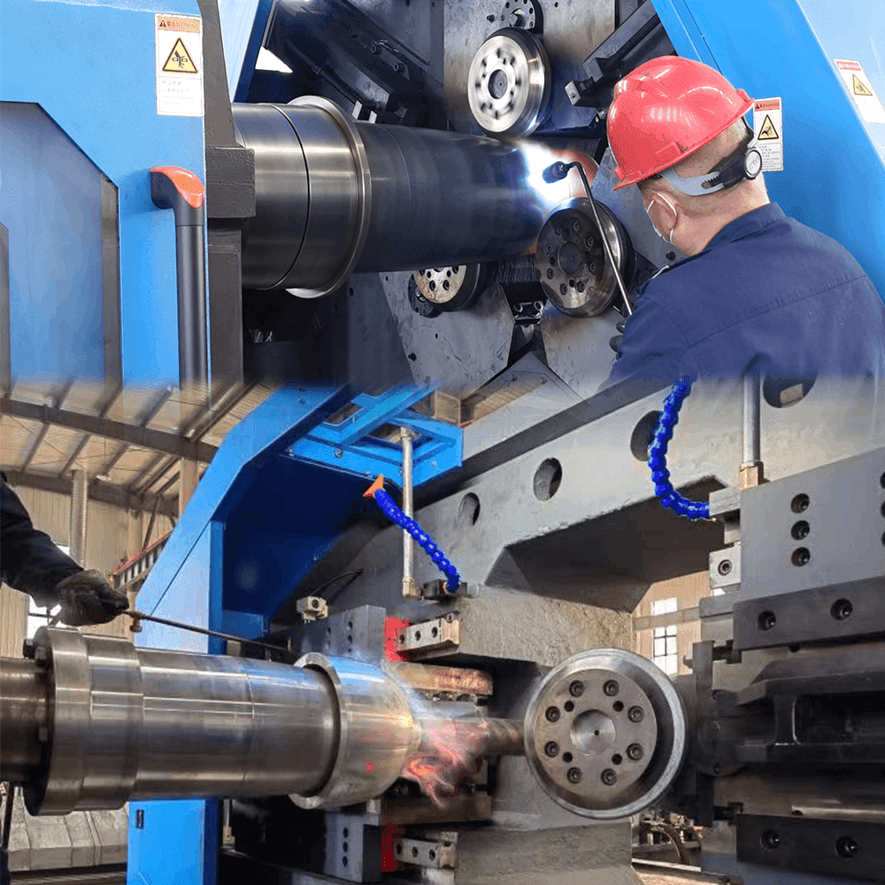
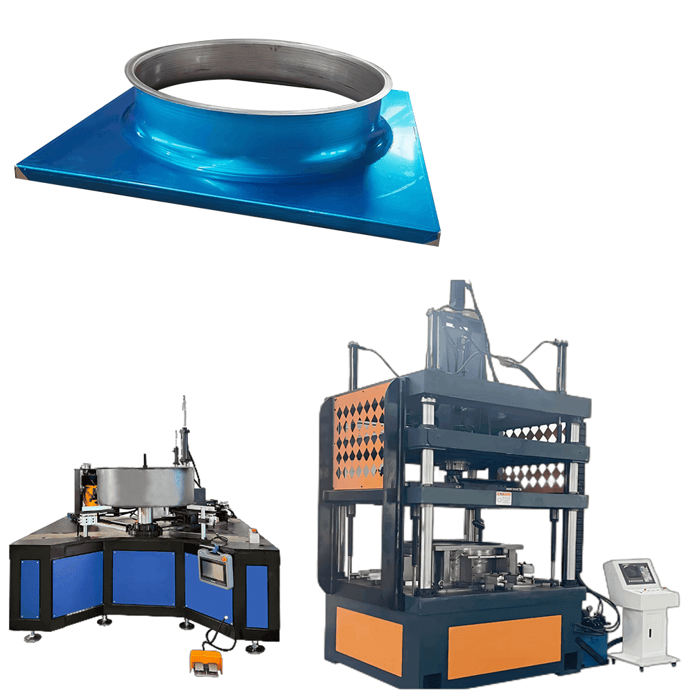
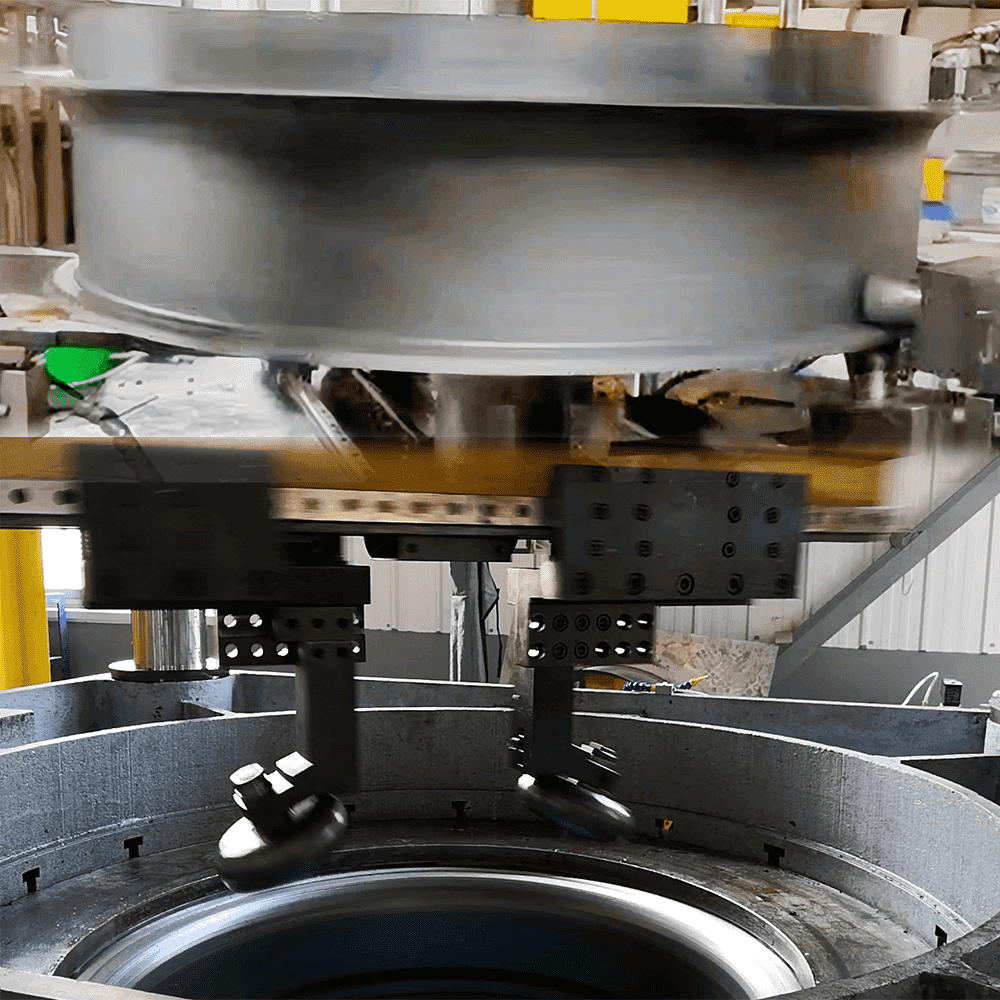
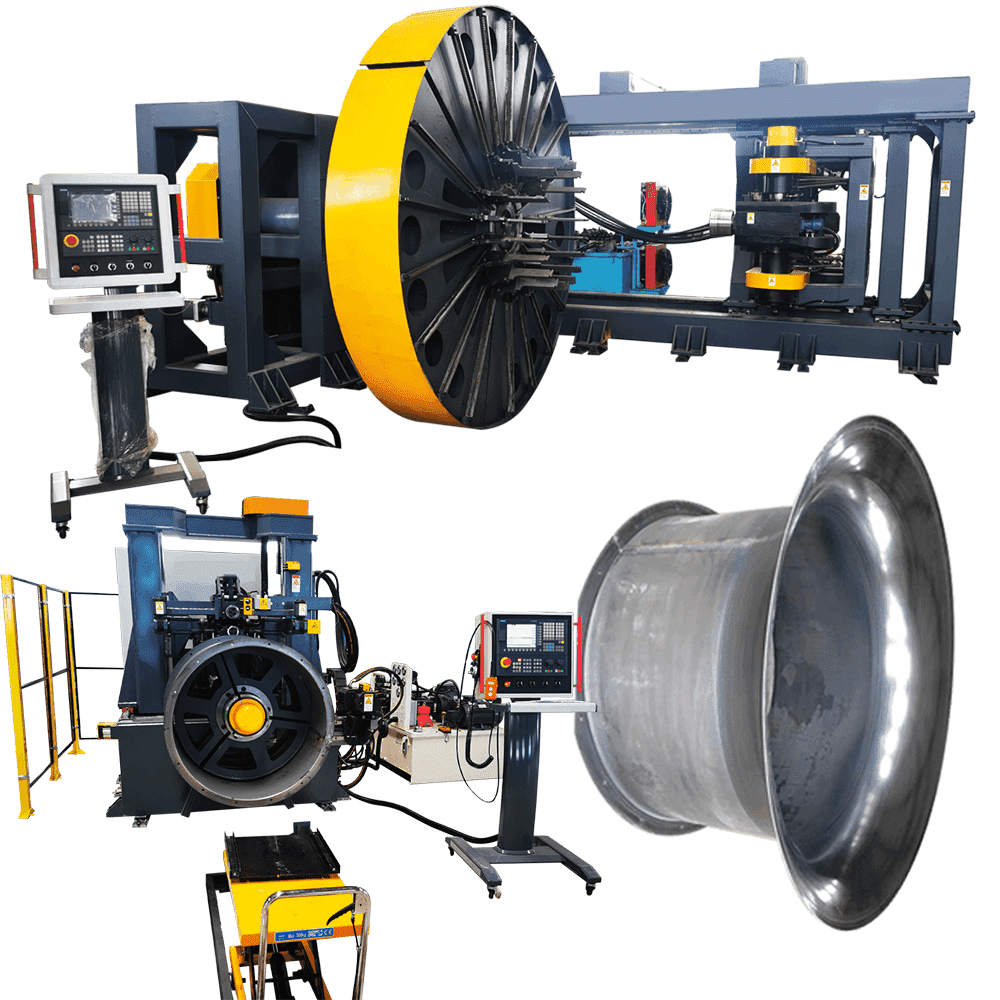
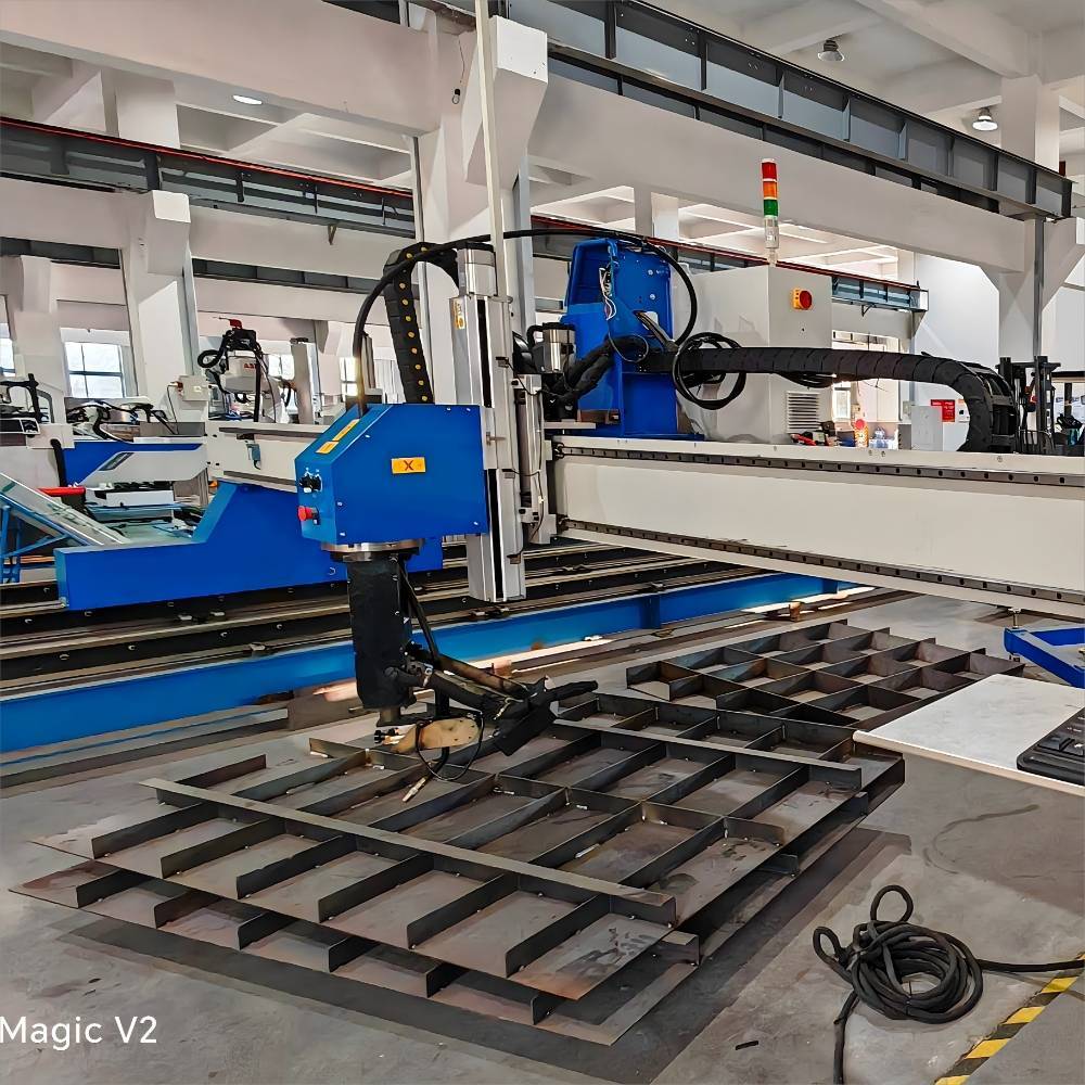
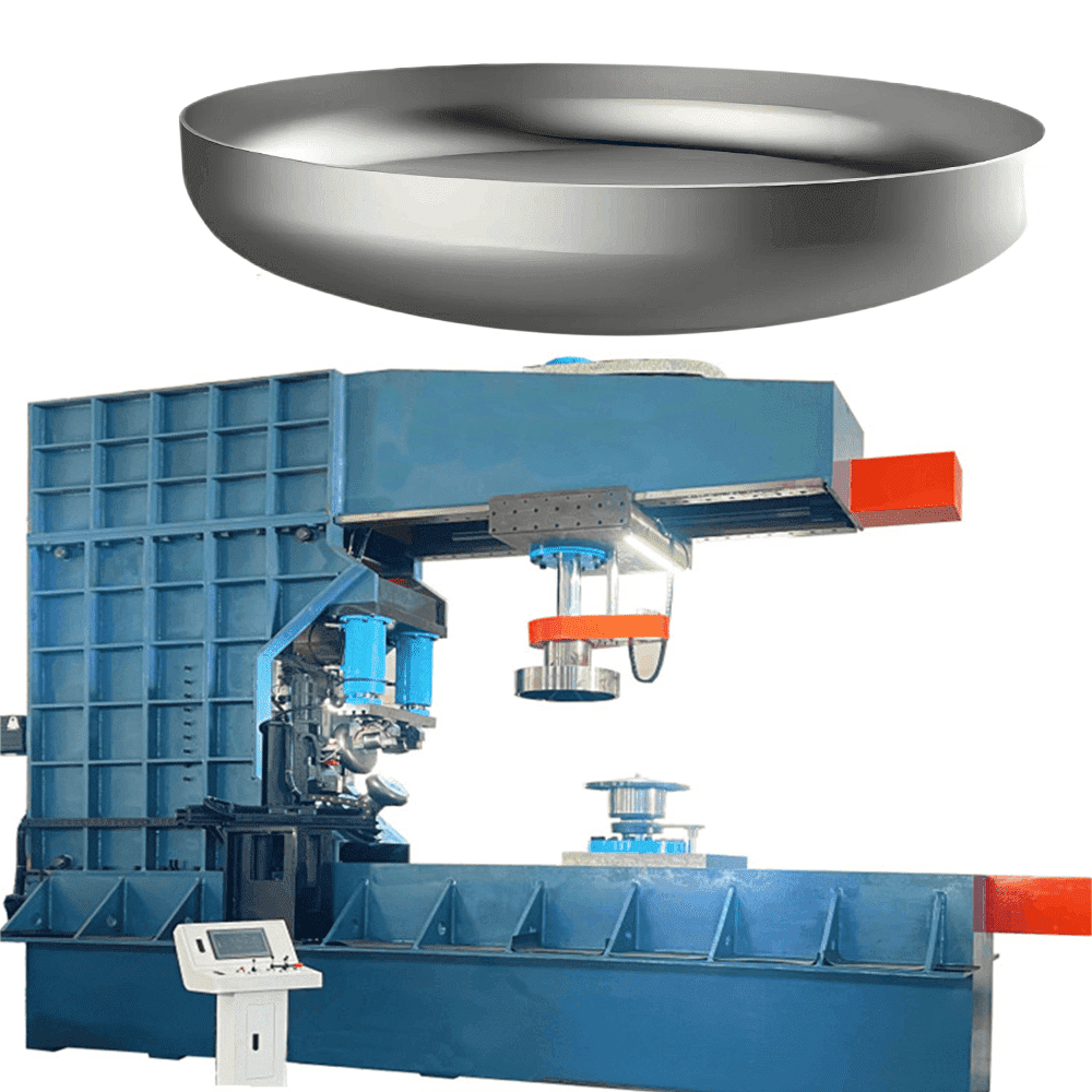
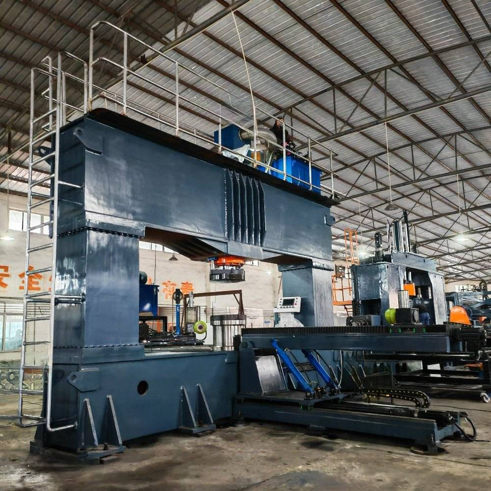
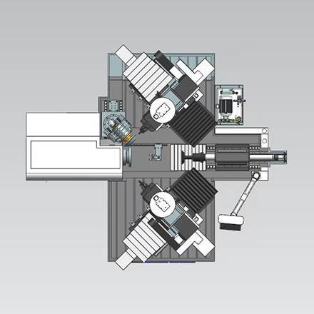
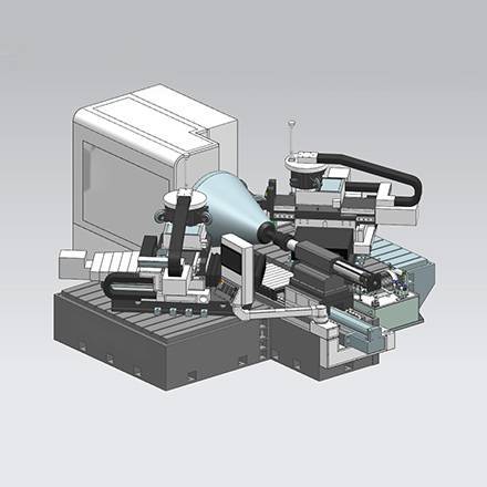
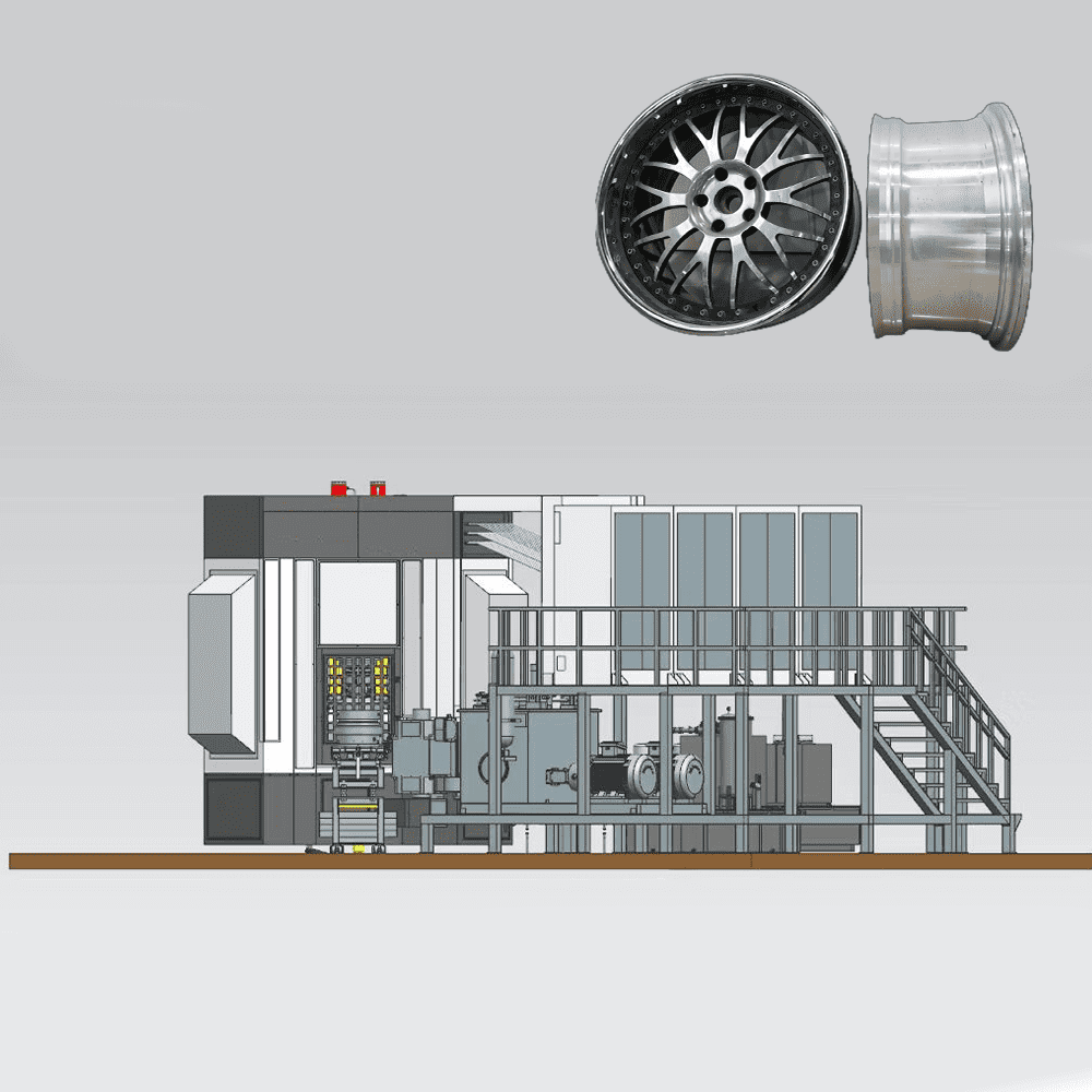
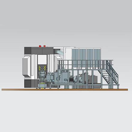
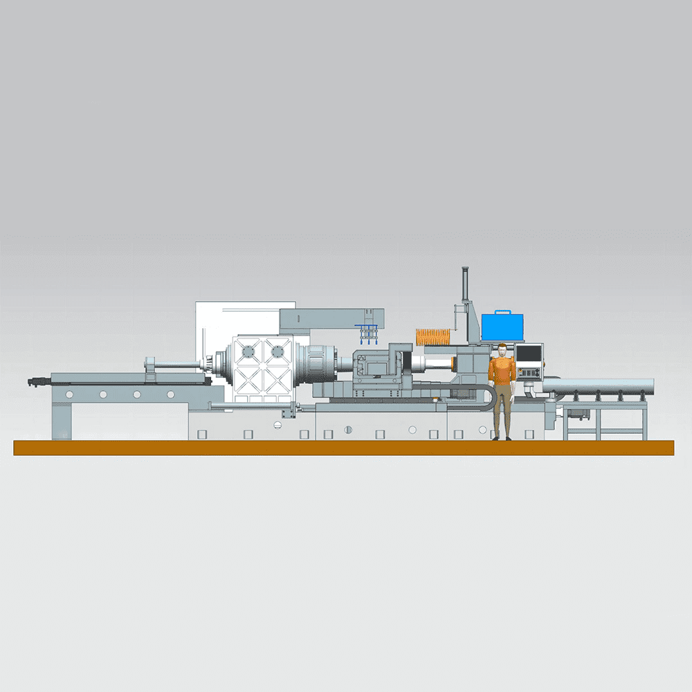
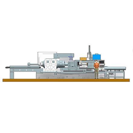
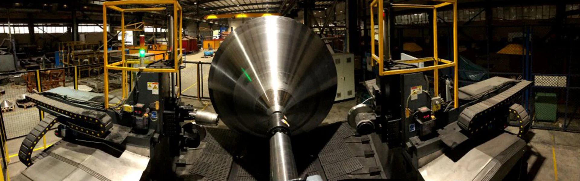
- √ High-precision CNC Metal Spinning Machines & Metal Flow Forming Machines, CNC Flanging Machine;
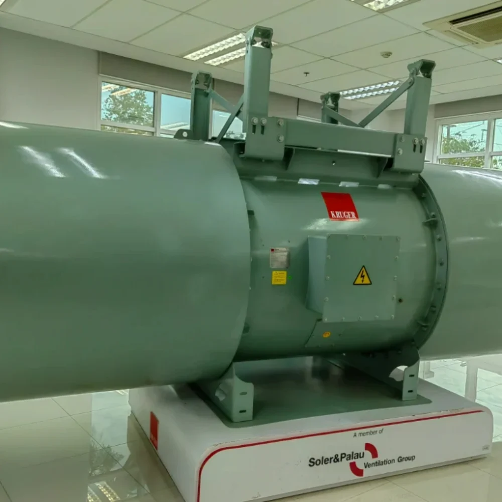
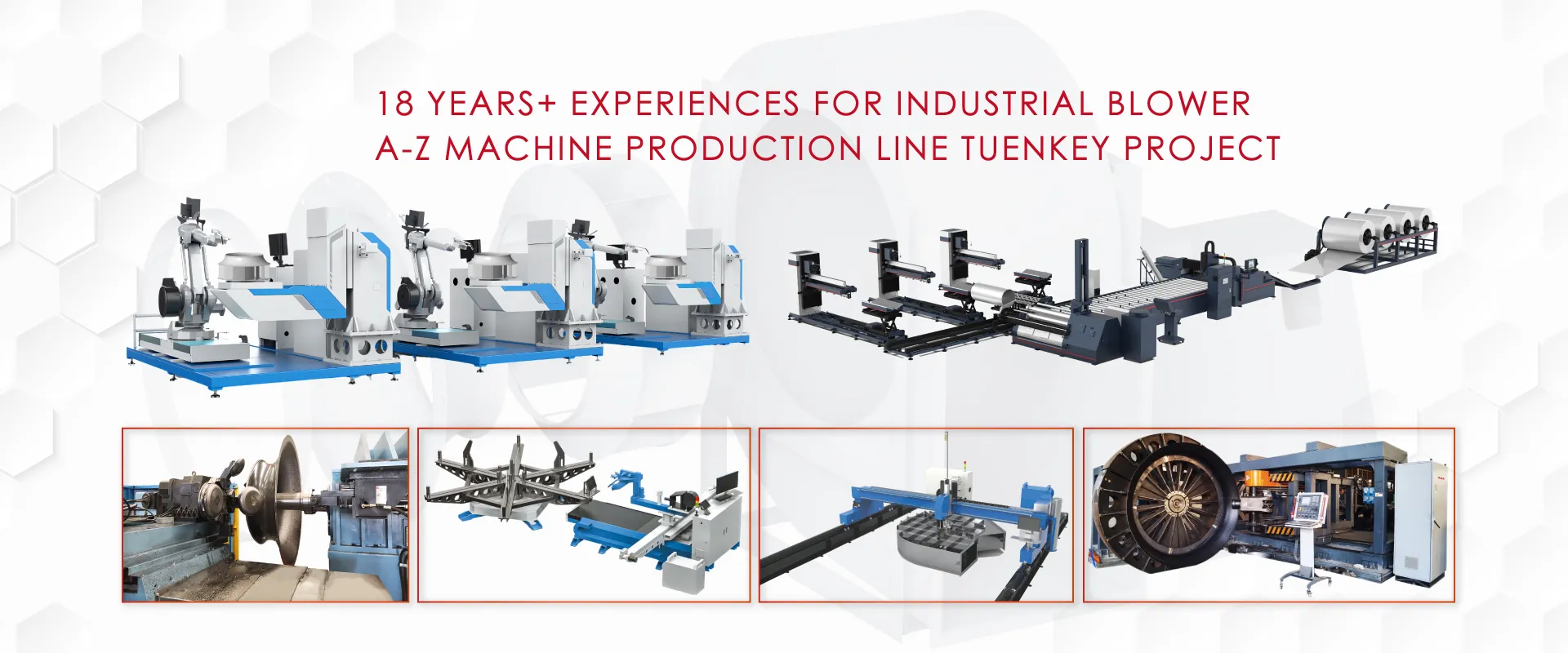
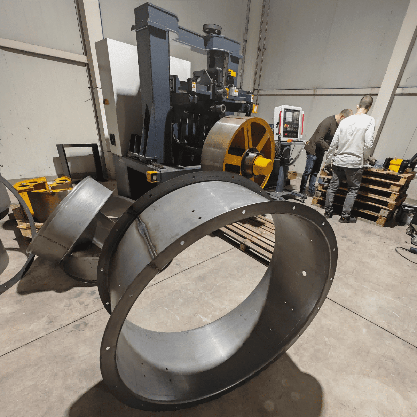
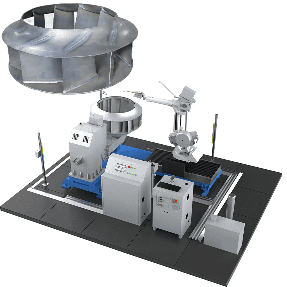
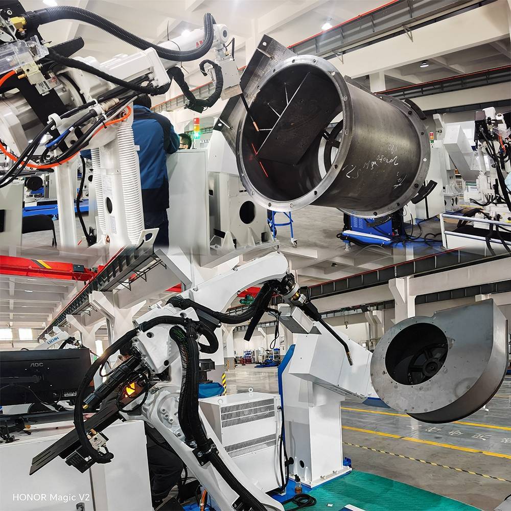
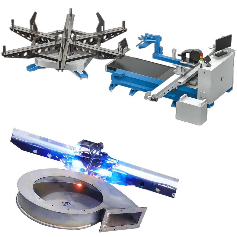
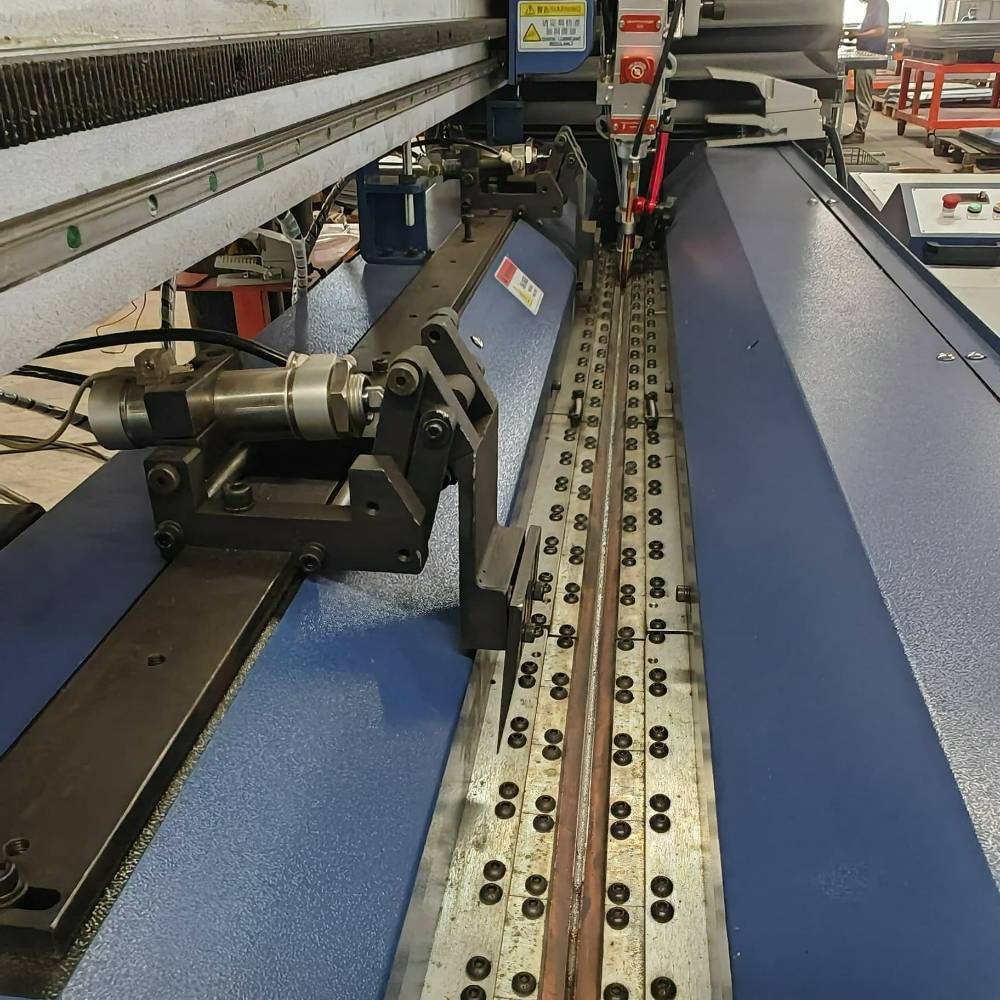
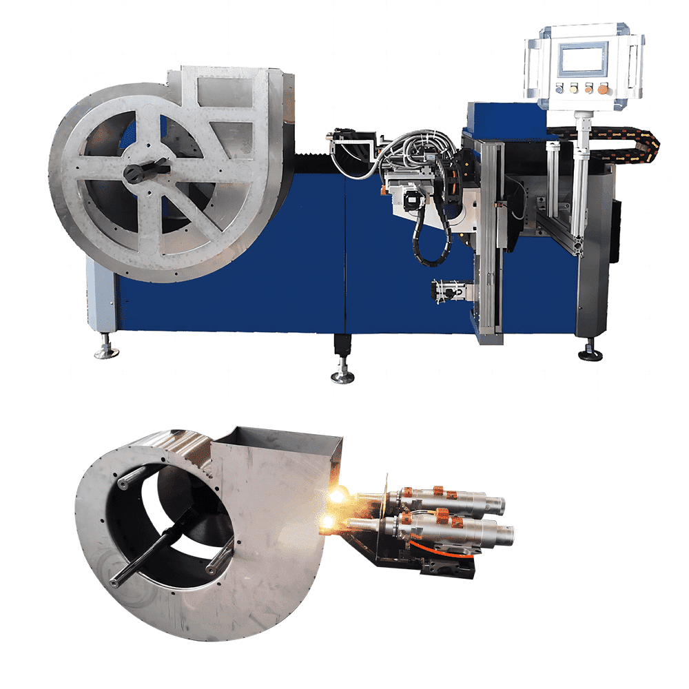
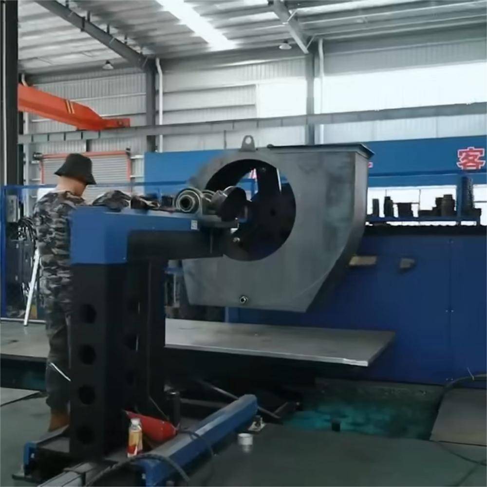
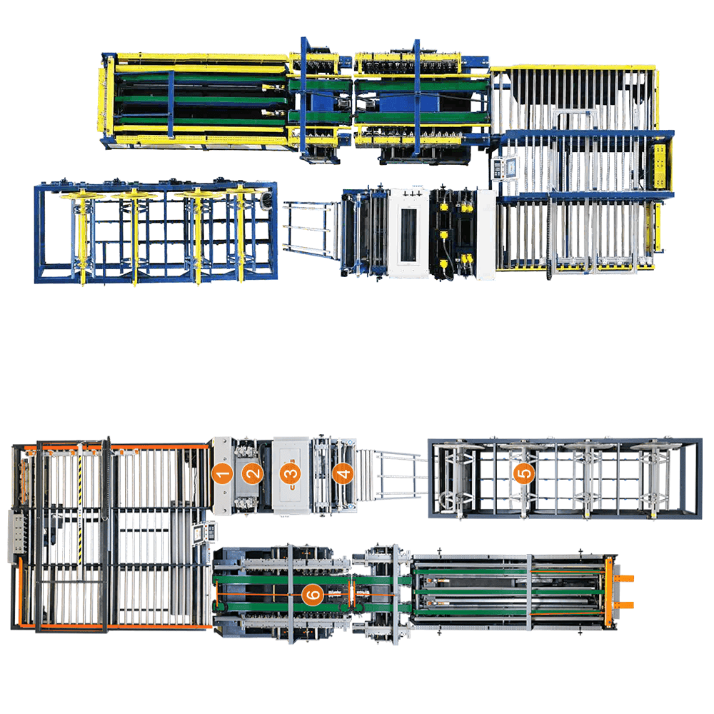
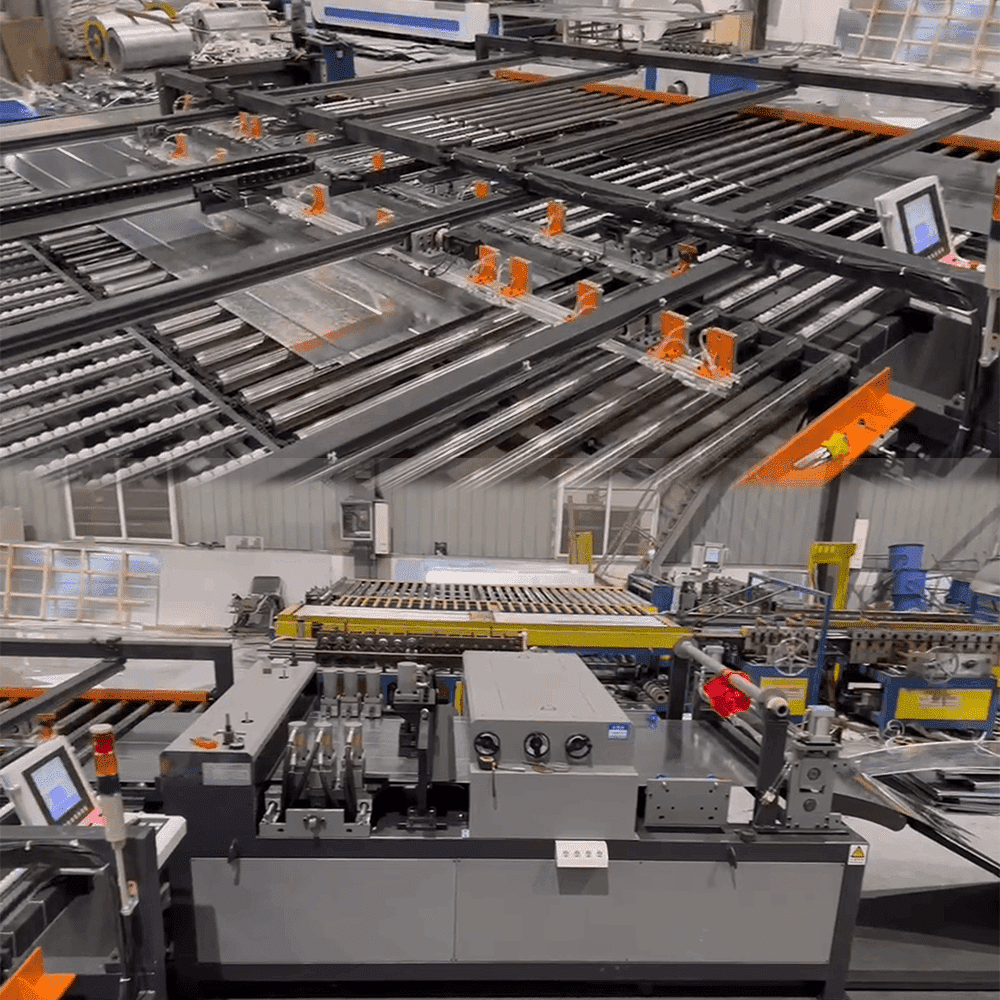
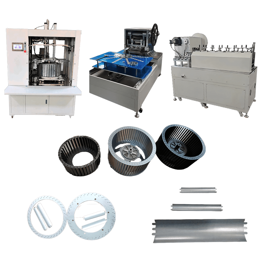
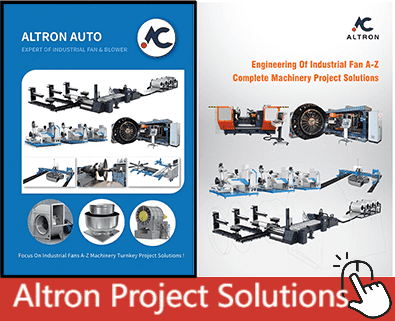
- √ Leading Industrial Fan Automation Production Line (Axial Fans and Centrifugal Fans) solutions;
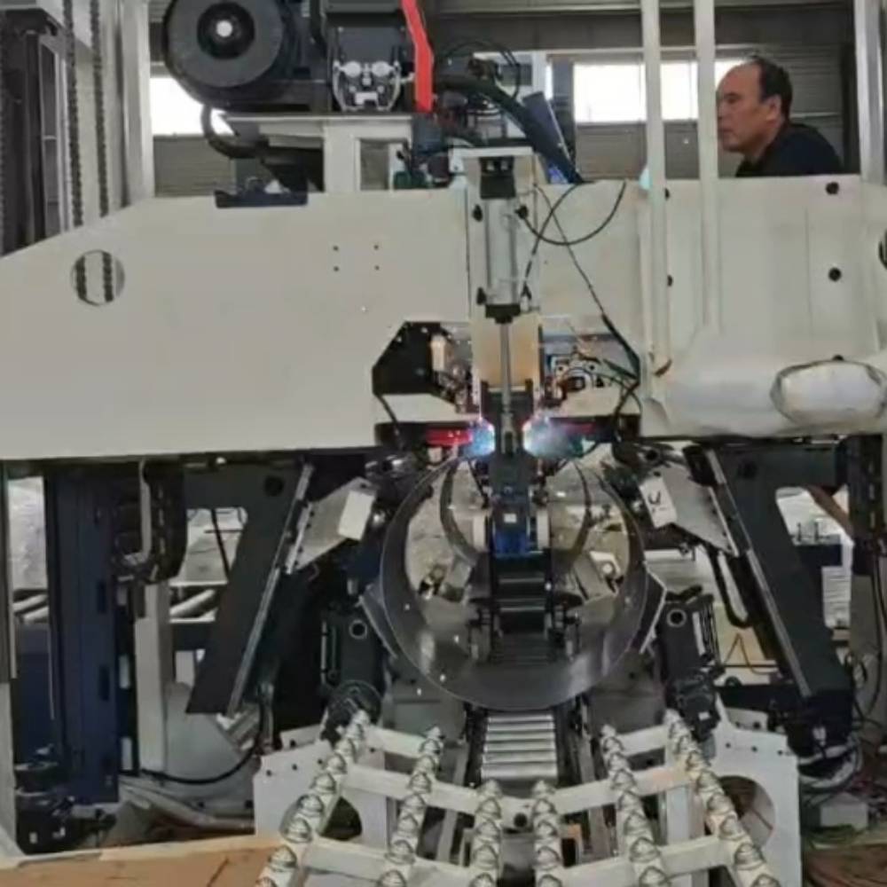
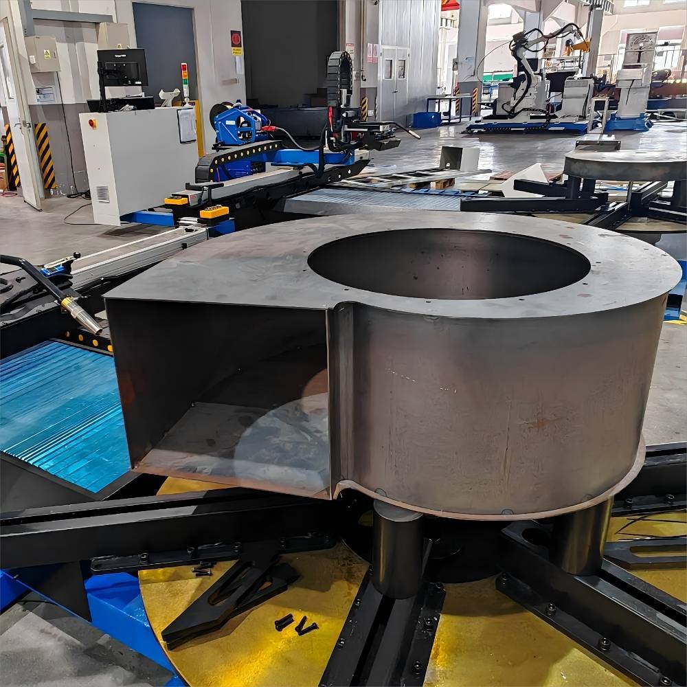
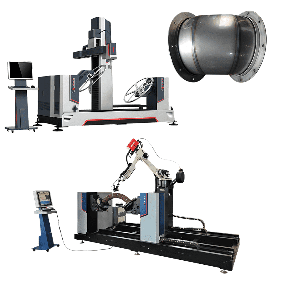
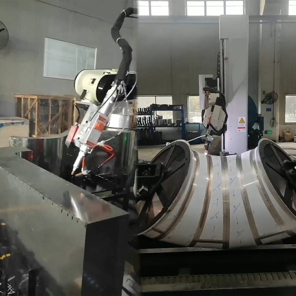
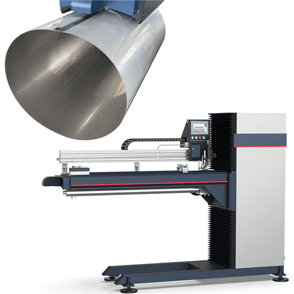
- √ Intelligent AI Visual Welding Robot solutions;
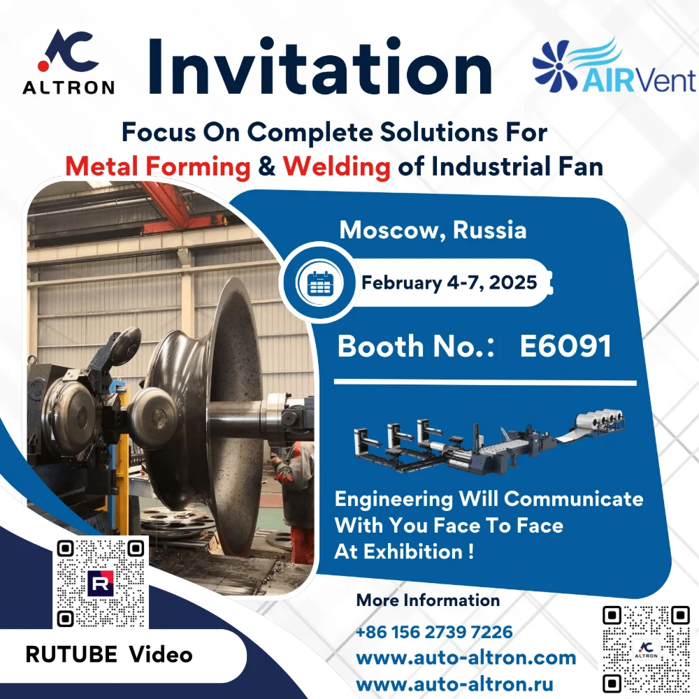
- √ Metal Forming and Automated Welding manufacturing process combination solutions;
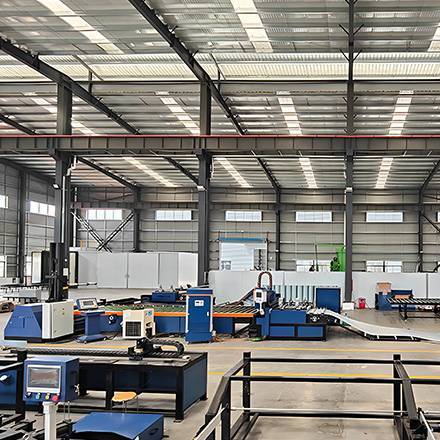
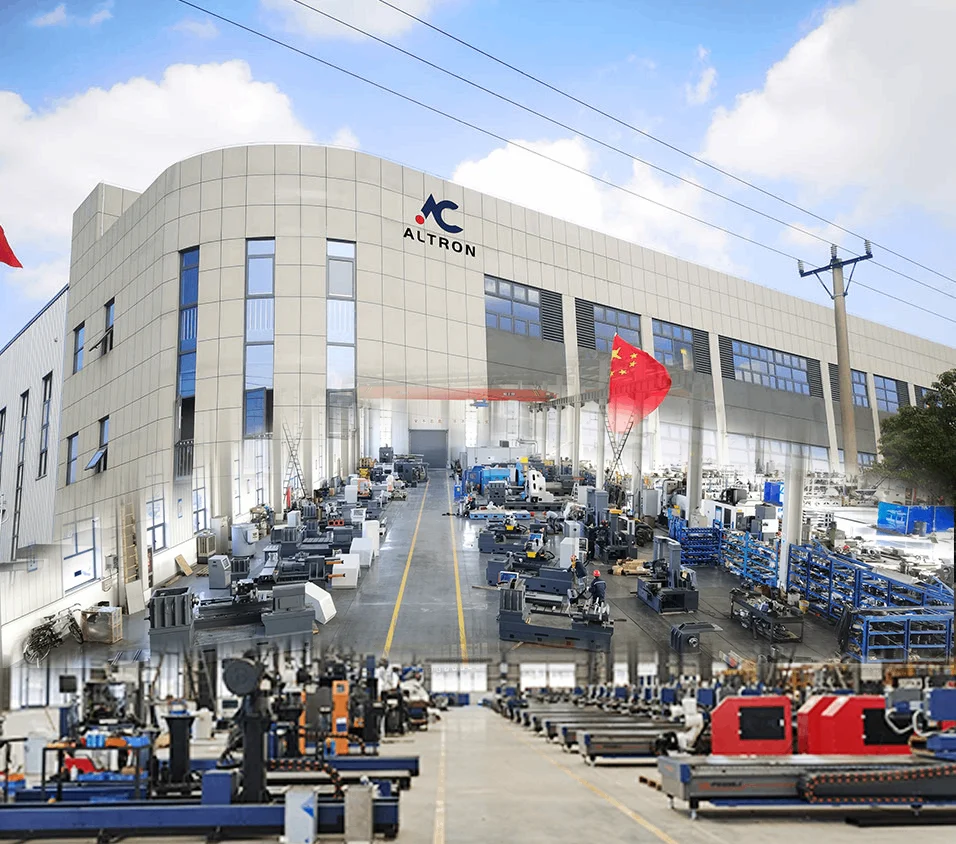
Altron’s R&D and manufacturing plants are located in Jiangsu & Guangdong, with a total area of more than 42,000 square meters for the factories and R&D bases.
Pre-Sales Guidance
Communicate Directly With Engineers Face-To-Face Via Google Meet.
Technical Training
Free Spinning Software & High-Quality Operation Technology Training.
Professional Service
Engineering Team Completed The Solution Within 2 Hours During Working Hours.
After-Sales Guarantee
7*24H Technical Online, Solutions Within 8 Hours During Working Hours.
PRODUCT VIDEO
CASE STUDIES
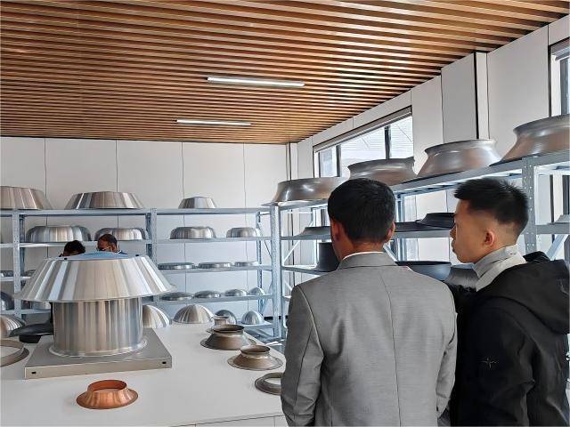
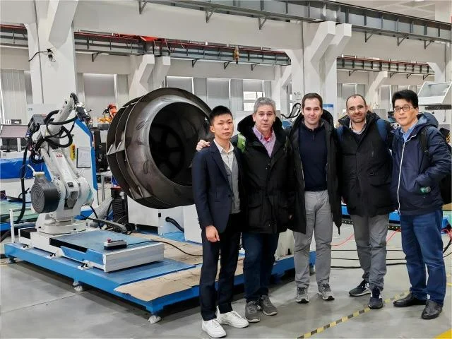
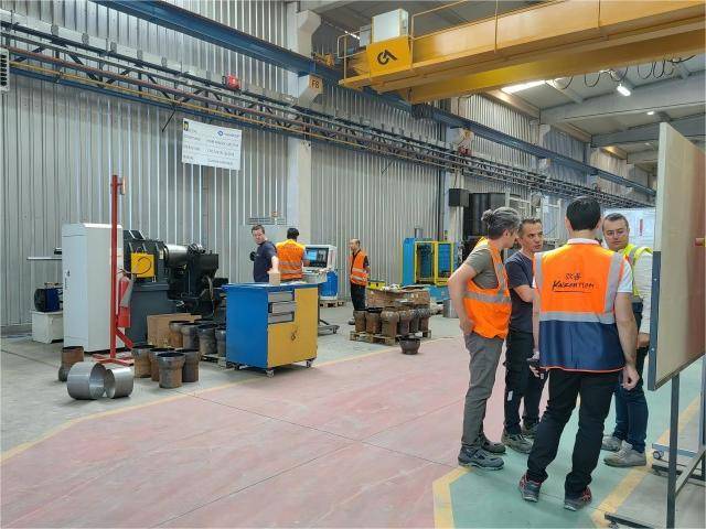
Focuses On Metal Forming & Welding A-Z Machinery Turnkey Project
Altron Manufactures And Provides Solutions For:
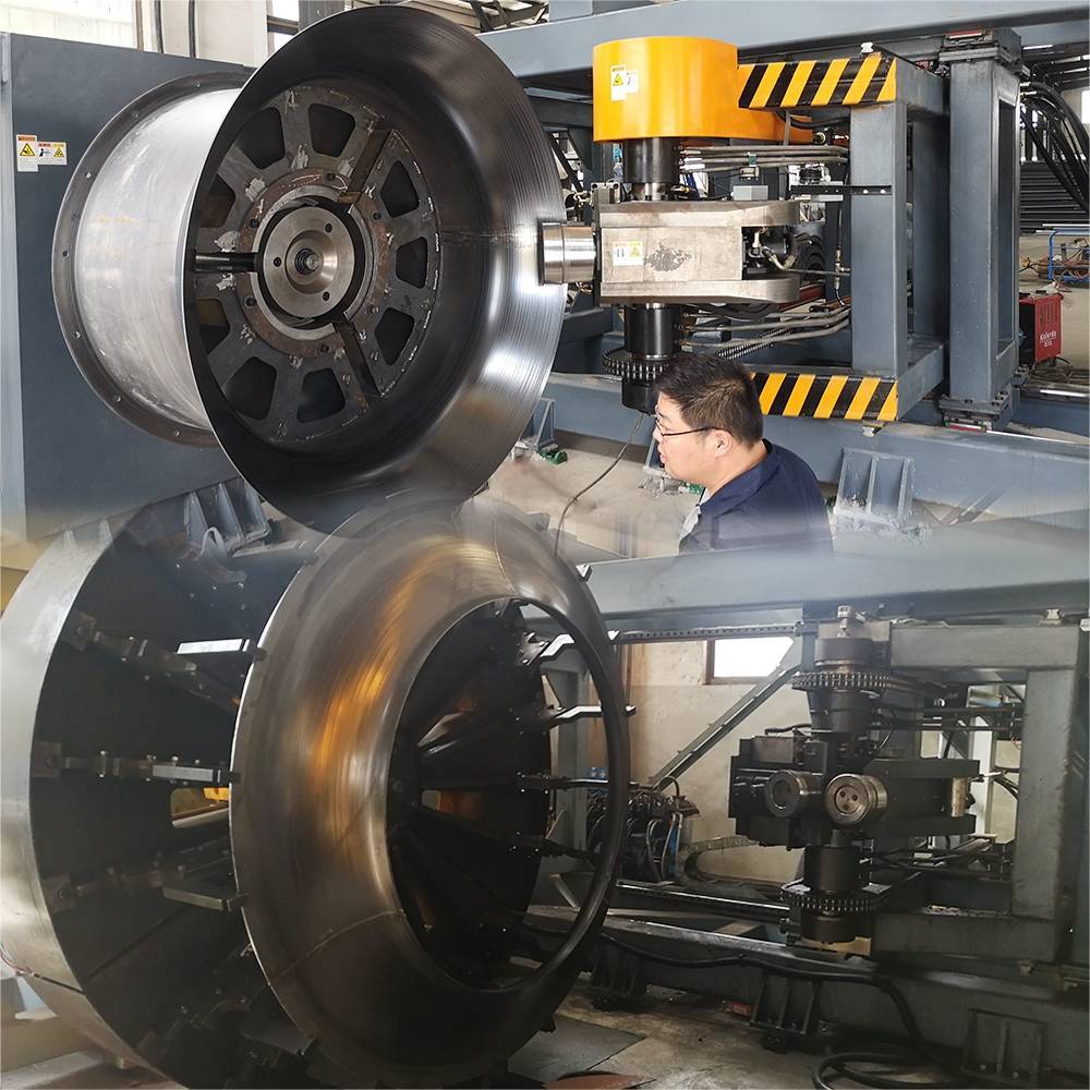
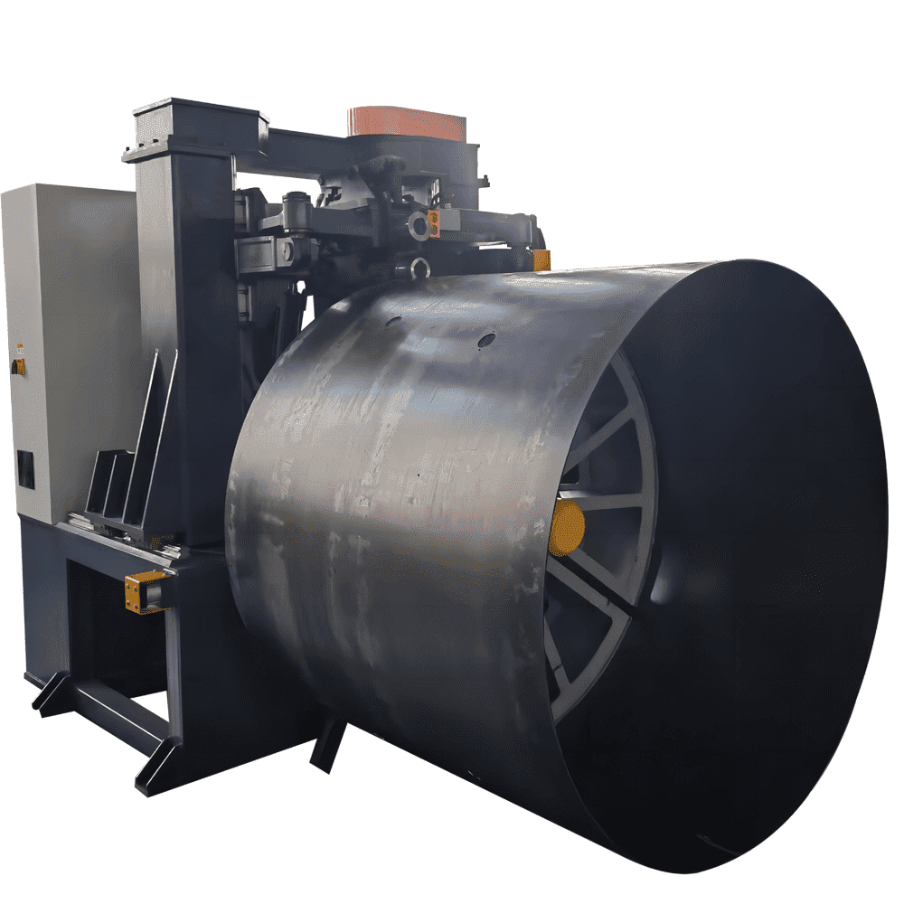
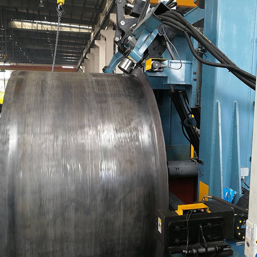
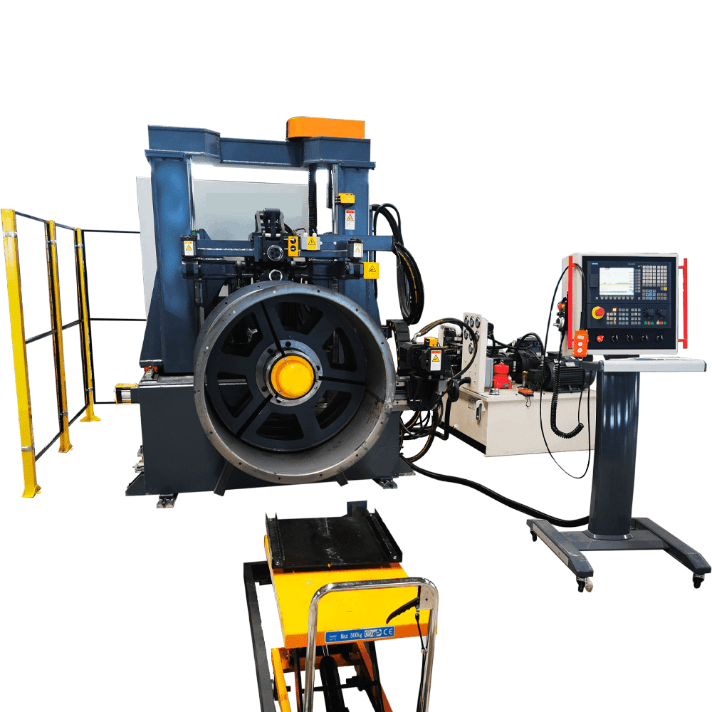
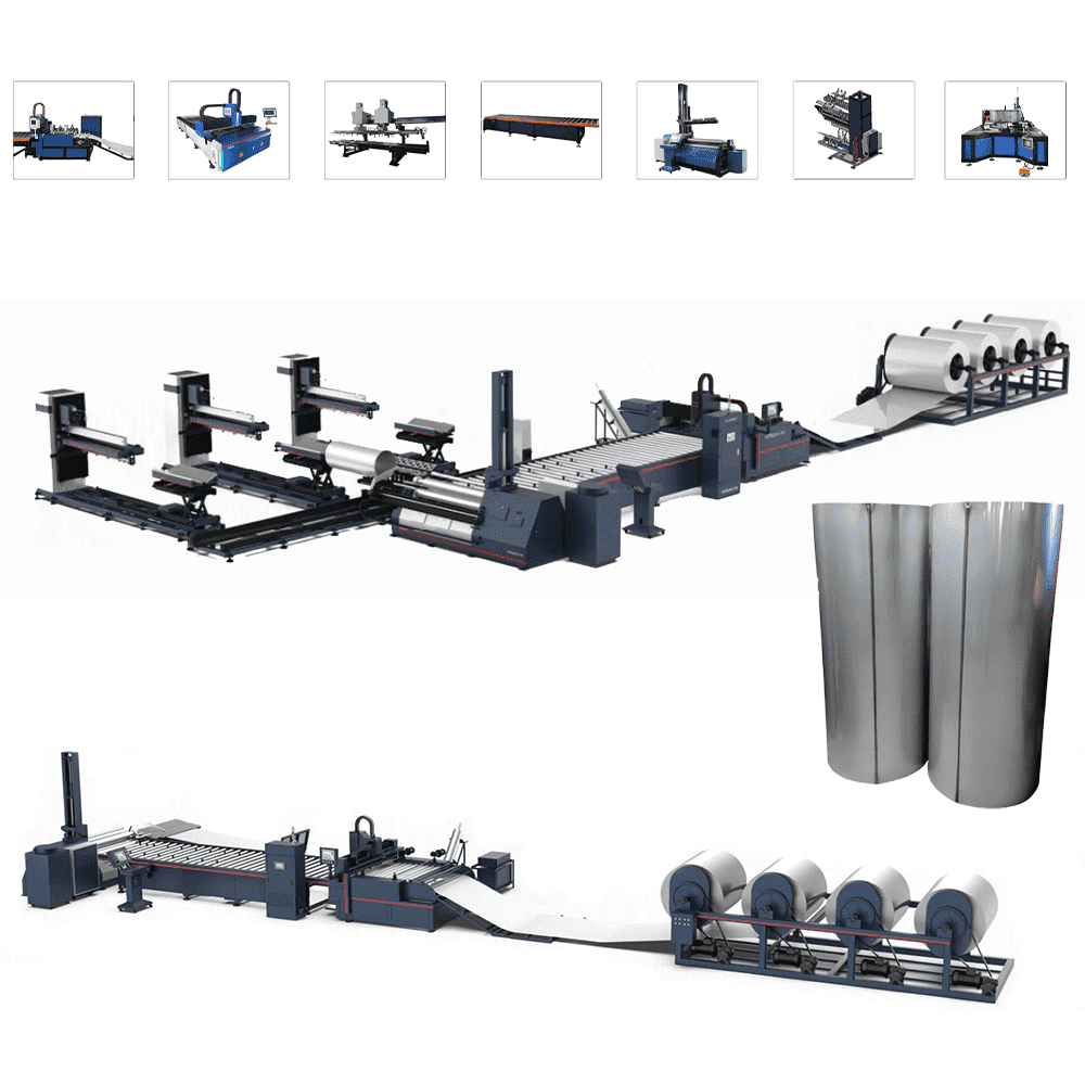
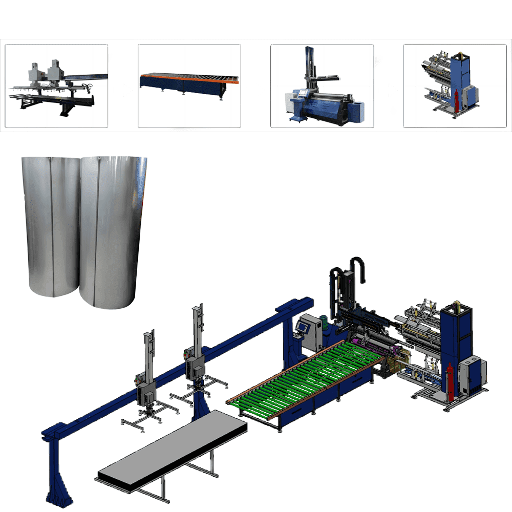
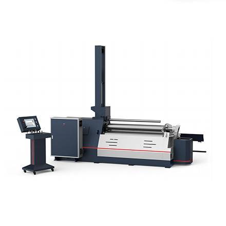
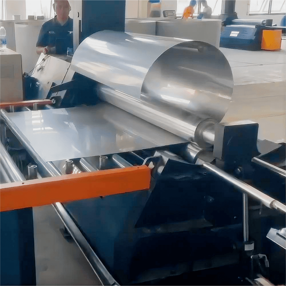
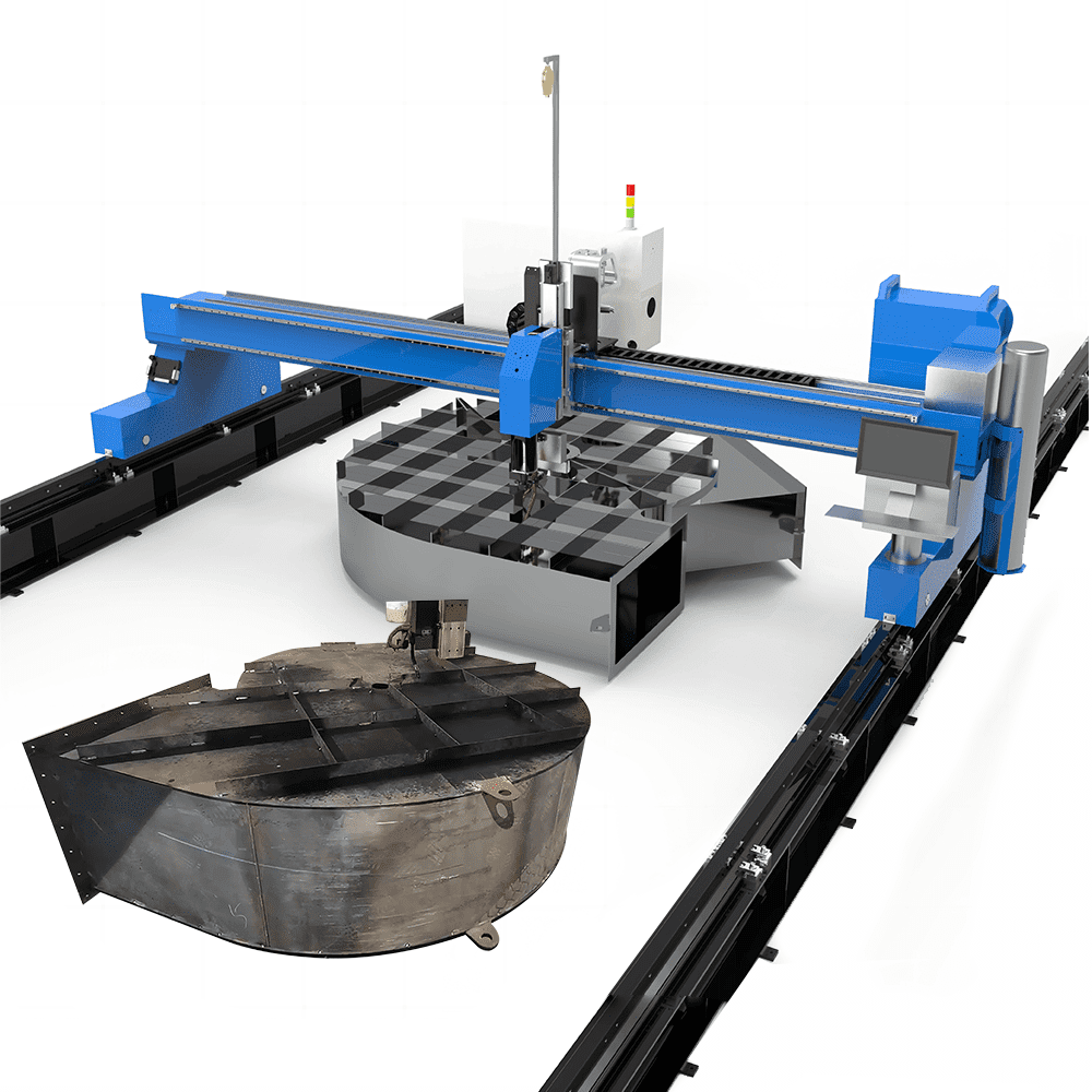
CNC Metal Spinning Machine, Multi-Roller Flow Forming Machine, Neck Spinning Machine, Internal Spinning Machine, Hub Spinning Machine, CNC Flanging Machine, Welding Robot, Rolling Machine, Seam Welding, Axial Flow Fan Production Line, Centrifugal Fan Impeller Welding, Centrifugal Fan Housing Welding, Air Duct Production Line, Spiral Duct Production Line, Rectangular Duct Production Line, Impeller Forming Production Line, Customized Industrial Fan Impeller, Laser Cutting Production Line, Laser Welding Solution, ect...
Corporate Headquarters:
Altron has 3 factories in China
1. Jiangsu, Changshu-Metal Forming Factory
2. Wuxi-AI & Visual Welding Factory
3. Guangdong, Zhaoqing-Auto Production Line Factory
4. Guangzhou-Sales Reception!
Email Address
Local Sales: crystal@auto-altron.com
Tel or Whatsapp
7*24 Quick Feedback
ALTRON-CATALOG
Get In Touch And Welding & Forming Technical Solutions !
1. Fill in your company information, Emial, Phone number and Project details;
2. Send product drawings and technical requirements to Altron;
3. Analyze drawings and determine technical solutions;
4. Quickly set up online meetings with customers to discuss technical issues and show Altron’s solution details;
5. After the customer confirms the plan, Altron will send a complete proposal and quotation!
Fill In Information